Loading…

Welcome to Red Current

Thermal Imaging Surveys

Specialising in Electrical, Mechanical and Building applications

1000 characters left
Electrical
Electrical
Buildings
Buildings
Mechanical
Mechanical
Underfloor Heating
Underfloor Heating
Leak Detection
Leak Detection
Housing Stock
Housing Stock
Thermal Camera Hire
Thermal Camera Hire
Thermal Camera Sales

Red Current also offer

Offshore thermography surveys

Thermography on Offshore Oil & Gas Platforms

Our PCN Level 2 Electrical Thermographic Engineers are trained and certified to the standards required by the Off-shore Oil and Gas industry in the UK and Europe.

Read more

BREEAM Thermography

Building thermography in support of BREEAM assessments

All building thermography surveys and reports are completed by UKTA Approved, PCN Level 2 thermographers as required in support of BREEAM assessments.

Read more

thermal camera hire

Thermal imaging camera hire - Free Delivery throughout the UK

Red Current stock a range of FLIR thermal imaging cameras available to hire. Cameras are delivered throughout the UK complete with report generation software.

Read more

Benefits of Electrical Thermal Imaging Surveys

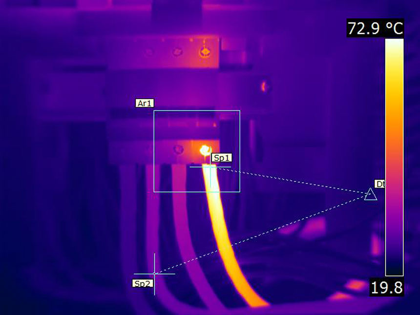
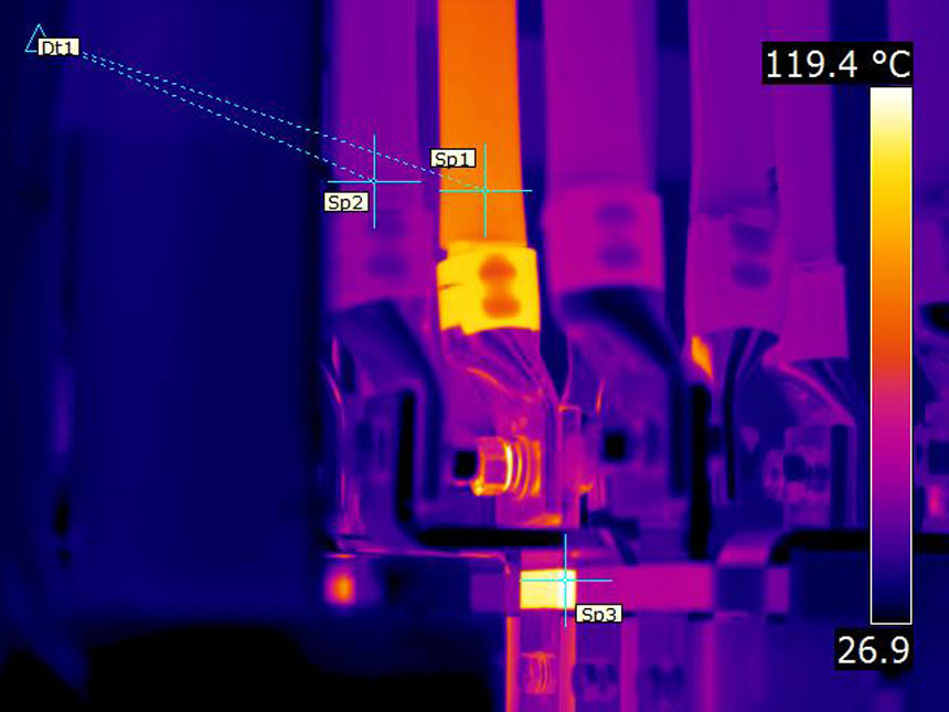
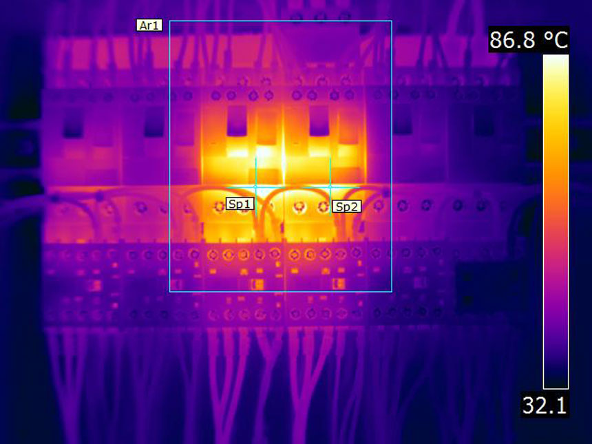
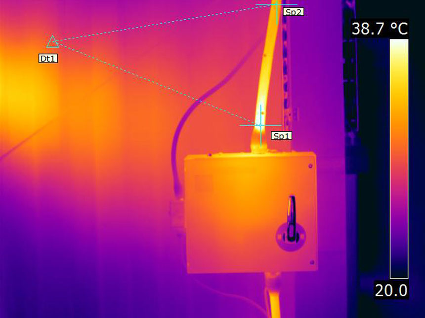
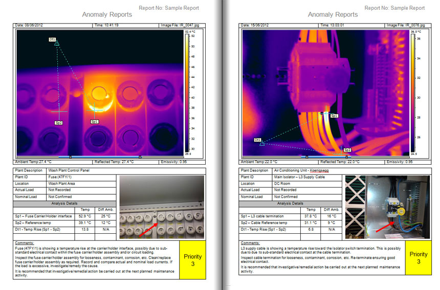
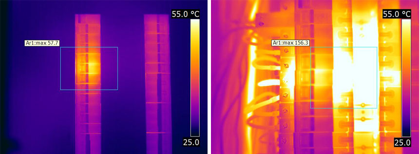
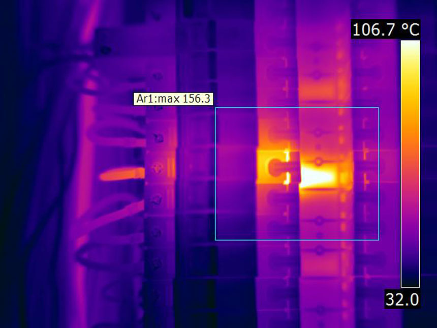
Thermography (thermal imaging) makes it possible to identify electrical defects such as loose connections and over loaded circuits (the most common cause of electrical fires), transformer cooling faults, motor winding faults and induced currents.

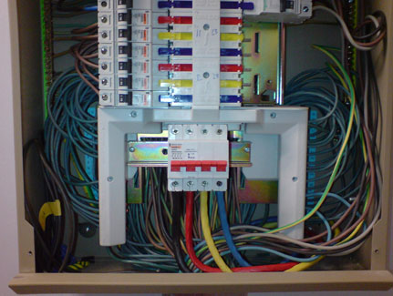
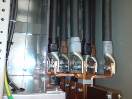
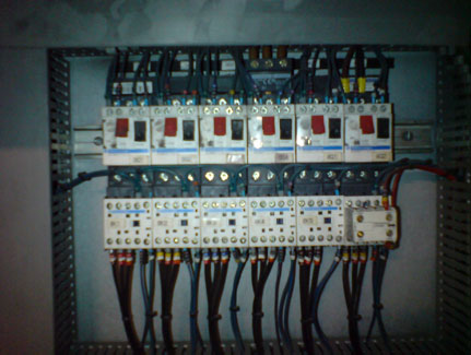
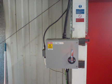
A thermographic survey inspects electrical equipment including distribution fuseboards, MCB boards, contactors, switch boards, transformers, motors, battery banks, UPS's, control panels, switch fuses and isolators etc whilst the equipment is in operation, causing no disruption to business operations.

Electrical thermal imaging surveys are non-intrusive, enabling inspections to be completed safely and efficiently, without interruption to your business operations. Appointing Red Current Ltd to undertake a thermographic survey of your electrical systems enables the following benefits to be realised:

Compliments the Periodic Fixed Wire Testing:

Electrical thermography identifies electrical issues that are unlikely to be detected during fixed wire testing and inspections.

Periodic Fixed Wire Testing is carried out to ensure that safety devices such as earth protection, fuses and circuit breakers operate as required under short circuit and fault load conditions. These devices provide no protection against the risks associated with poor connections.

Thermal Imaging should be carried out following fixed wire testing to ensure poor connections have not been introduced during the Fixed Wire testing activity.

Surveys are non-intrusive…… no disruption to normal business operations.

There is no other technique that is able to identify electrical issues such as poor connections, overloading, phase imbalances, faulty equipment etc. as safely and as quickly. A thermographic survey is non-intrusive, meaning no disruption to normal business operations.

Enables any requirement for intrusive maintenance to be planned around normal business operations.

Electrical thermography enables the identification of only those items of equipment that require remedial works together with the severity of the defect. This enables maintenance to be suitably planned around operational commitments maximising the availability of plant and equipment.

Potential to extend equipment lifecycle and identify energy savings.

A thermographic survey can give an excellent insight into the operational effectiveness of equipment, enabling the identification of opportunities to make energy savings together with increasing the operational lifecycle of equipment.

Reduction in the cost of breakdowns

Depending on the type of equipment and its location, the cost of electrical failure can run into many thousands of pounds in repairs, lost production, injury claims, etc.

As defects are found before they cause equipment to fail, the associated cost of repairs is minimal compared to the cost of equipment failure.

Thermal Imaging of Electrical Distribution Boards

Below shows a thermal image recorded of an MCB distribution board during an electrical thermal imaging survey within a data centre electrical switch room.

As can be seen in the thermal image below, there is a temperature rise toward the blue/L3 supply cable termination which was due to poor electrical contact at the cable termination and within the switch assembly.

Analysis Details

Temp

Diff Amb

Sp1 - Cable Termination 73.4°C 48°C
Sp2 - Cable Reference Temp 30.2°C 5°C
Ar1 - Maximum Temp 130.1°C 105°C
Dt1 - Temp Rise (Sp1 - Sp2) 43.3°C n/a
visual image of distribution board
thermal imaging of distribution boards

Contact Red Current Today

contact redcurrent today

Got a question?

Give us a call on 0118 3320819 or submit your enquiry to our team who are on hand to assist.

Due to the temperature recorded and the importance of the equipment, this anomaly was given a priority 1 category requiring urgent action to be carried out.

The engineering team were fully informed of the defect who immediately took action to reduce the load from the distribution board which immediately reduced the fault temperatures enabling full remedial works to be scheduled around business operations.

If this defect were left undetected there was a significant risk of fire which would have resulted in power loss to multiple server racks causing the data centre to be offline until power was restored.

The use of thermography enabled the defect to be identified in time to enable remedial works to be planned and executed before failure occurred. To find out more about the benefits of electrical thermal imaging surveys contact us today with your enquiry.

Thermal Imaging of Switch Panels

Below shows a thermal image recorded of the supply cables to the main switch panel during an electrical thermographic survey within a data centre in East London.

As can be seen in the thermal image below, there is a temperature rise toward the L1 supply phase cable termination which was due to poor electrical contact between the cable lug and busbar assembly.

Analysis Details

Temp

Diff Amb

Sp1 - Cable temp (L1) 85.4°C 61°C
Sp2 - Cable temp (L2) 46.8°C 23°C
Sp3 - L1 Busbar temp 119.2°C 95°C
Dt1 - Temp Rise (Sp1 - Sp2) 38.6°C n/a
switch-panel-incomer
switch-panel-incomer-ir

Contact Red Current Today

Contact Red Current Today

contact redcurrent today

Got a question?

Give us a call on 0118 3320819 or submit your enquiry to our team who are on hand to assist.

Due to the temperature recorded and the importance of the equipment, this anomaly was given a priority 1 category requiring urgent action to be carried out.

The Engineering Manager was immediately informed who took emergency action to supply the datacentre through alternative means whilst the lug connection was suitably tightened to the recommended torque.

This anomaly was identified just in time before irreparable damage was caused to the cable. If left for much longer the cable temperature would have likely increased to the melting point of the cable presenting a significant risk of short circuiting and explosion, leading to considerable business interruption losses and large repair costs.

To find out more about the benefits of electrical thermography surveys contact us today with your enquiry.

Thermal Imaging of Control Panels - Contactor Overload

Below shows a thermal image recorded of two contactor overloads within an electrical control panel supporting Foundry process.

As can be seen in the thermal image below, the overload bodies are hot possibly due to incorrect selection or settings of the overloads for the driven load (fan motors).

Analysis Details

Temp

Diff Amb

Sp1 - Overload Body 3Q3 96.1°C 62°C
Sp2 - Overload Body 3Q4 89.5°C 55°C
Ar1 - Maximum temp in area 110.1°C 76°C
contactor-overloads
contactor-overloads-ir

Contact Red Current Today

Contact Red Current Today

Contact Red Current Today

contact redcurrent today

Got a question?

Give us a call on 0118 3320819 or submit your enquiry to our team who are on hand to assist.

Load measurements were recorded by the Engineering team on site which were then compared to the design specifications of both the overloads and driven load. This revealed that the load was too high which was later found to be due to filters being blocked within the process. The filters were then replaced which reduced operational load on the fan motors to within the design settings for the overload and fan motors.

The above example shows that in the right hands, thermography is an excellent predictive maintenance tool than can provide a superb assessment of the operational performance of process related equipment.

To find out more about thermal imaging of electrical equipment contact us today with your enquiry.

Thermal Imaging of Switch Fuses and Isolators

Below shows a thermal image recorded of an isolating switch supplying an air compressor.

As can be seen in the thermal image below, there is a temperature rise toward the cable terminations on the supply side of the switch. This was due to poor electrical contact at the cable terminations. Note that the isolator cover could not be opened as it was mechanically interlocked.

Analysis Details

Temp

Diff Amb

Sp1 - Cable temp 40.8°C 19°C
Sp2 - Cable reference temp 33.1°C 11°C
Dt1 - Temp rise (Sp1 - Sp2) 7.7°C n/a
switch-fuse
switch-fuse-ir

Contact Red Current Today

Contact Red Current Today

Contact Red Current Today

Contact Red Current Today

contact redcurrent today

Got a question?

Give us a call on 0118 3320819 or submit your enquiry to our team who are on hand to assist.

Although the temperature rise was only 7.7°C, the temperature at the cable terminations within the switch were likely to be significantly hotter. Therefore the anomaly was assigned a priority category of Level 2 requiring attention at the earliest opportunity.

The Engineering Team scheduled a shutdown of the compressor to carryout investigative/remedial works. Shortly after shutting the equipment down, the team used their own thermal imaging camera and recorded temperatures inside the isolator in excess of 90°C.

The cables were all re-terminated and the switch mechanism was replaced before re-commissioning the equipment.

The above example shows how important it is to take into consideration possible temperatures at the source of the defect, such that the priority given to remedial works is suitable to prevent damage and unplanned production downtime.

To find out more about the use of thermography for electrical inspections contact us today with your enquiry.

Will the thermographic report satisfy the requirements of my insurance?

Red Current’s thermographic survey approach and reporting structure has been set up to satisfy the requirements expected by insurance companies, Safety auditors, Maintenance/Engineering Managers, etc. Survey reports comprises of four sections:

1. Introduction/Report Summary – This provides detail on the survey carried out together a top level summary of the overall findings.

2. Main Body Report Pages – Where faults/anomalies are identified, an individual report page is produced providing a description of the fault, its severity and recommended remedial action.

3. Condition Monitoring Assessment – These pages provide an understanding of the current operational condition of equipment that have been reported during previous surveys.

4. Appendices – These pages provide a checklist and images of every asset inspected during the survey. This provides an auditable record of what was inspected, together with equipment health at the time of the survey.

electrical sample report

All electrical thermographic surveys are carried out by Electrically qualified thermographic engineers, certified to ISO 18436-7. Our survey approach follows a strict set of thermal imaging standards with method statements which have been suitably risk assessed and dove tails with local/company specific safe working procedures.

Why should thermographic surveyors be certified when undertaking thermal imaging surveys on electrical equipment?

Although thermal images often appear to be self explanatory when presented in a thermographic report, correctly identifying defects/anomalies in the first place relies on two key factors:

  1. The thermographer’s understanding of the construction and operation of the electrical systems together with its possible failure modes.
  2. The thermographer’s ability to interpret what he/she is observing when using a thermal imaging camera such that the correct conclusion is drawn and presented within the report.

Without these two factors in place, there is very real risk that anomalies/defects are misunderstood and incorrectly reported. For instance reporting supposed defects which are in fact operating normally, or even worse missing/not identifying actual defects.

To prevent this risk, the use of a thermographer that is certified to ISO 18436 is vital. The certification scheme ensures that thermographers have been suitably trained, with their knowledge assessed and have accumulated the required amount experience in undertaking thermographic surveys within the electrical application of thermography.

Red Current follow a strict set of thermal imaging standards and only employ thermographers that are certified to ISO 18436, therefore you can be assured that the thermographer undertaking thermographic surveys in your facility will possess the two key factors discussed above.

Do covers need to be removed from electrical distribution boards?

The short answer to this is yes.

The use of thermography as a predictive maintenance tool is to identify anomalies such as poor connections as early as possible to enable remedial activities to be scheduled with minimum business interruption.

A poor connection can be identified at temperatures only a few degrees above ambient therefore unless the infrared camera is able to see through the panel covers, (which they can't) it is simply impossible to identify this type of fault in the early stages.

There are times when it may not be possible to remove covers for example:

  • the cover is mechanically interlocked with the supply isolator
  • the Health and Safety risk associated with removing the panel cover is unacceptable
  • in the case of MCB boards, the risk of inadvertently switching off an MCB whilst removing the cover will cause unacceptable business interruption

In the cases above it is still worthwhile surveying equipment with the covers on, as if the connection is bad enough, it may be possible to detect a fault before too much damage has occurred. It is very much a case of something is better than nothing. It should be recognized that if an anomaly is detected with the covers on, it is likely to require urgent attention which can create significant pressure on those in charge of managing maintenance activities around business operations.

The thermal images below show an MCB board both the cover on and with it removed. As can be seen from the image on the left, there is little sign of anything wrong as MCBs under load will operate at temperatures up to 60°C. However with the cover removed (Right), the prognosis is quite different.

Covers-on-vs-covers-off

The image below shows the right hand image again, this time thermally focused. From this it is clear to see that the cause of the temperature rise is due to a poor connection between the supply side of the MCB and distribution board busbar assembly.

MCB-with-cover-removed

To find out more about the use of thermography on electrical equipment contact us today with your enquiry.

Get an estimate today*

*Within our normal office hours

Thermographic Survey Estimate

Receive an estimate by email within the 24 hours

Our Clients

AT&T
Biffa
Debenhams
Thames Water
Dunlop
 Maresk Oils
Mitie
Mulberry
Southend University Hospital
Northern Offshore
Rolls Royce
Sentinel
The Co-Operative
Total
Virgin Media
Howden
Marsh

Latest Testimonial

Rollalong Ltd required a thermal imaging survey in support of a BREEAM assessment on two newly constructed facilities for the MOD. We instructed Red Current Ltd as they had the required Level 2 Thermography certification and were competitive on price. The survey was carried out within the agreed timescale with the subsequent report clearly presented identifying recommendations for further investigation. We would recommend Red Current Ltd to any other company requiring a thermal imaging survey.

Nick Wilson, Rollalong Ltd

rollalong logo

Please contact us with your thermal imaging camera hire request

Powered by ChronoForms - ChronoEngine.com

Data Privacy: To find out how we process the data that you submit to us via this form, please read this Privacy Statement.

Invoice Enquiry

Please fill out this form for us to generate an invoice. Call us on 0118 3320819 or email your enquiry to our team who are on hand to assist.

Data Privacy: To find out how we process the data that you submit to us via this form, please read this Privacy Statement.

Powered by ChronoForms - ChronoEngine.com